| 3.7. Geometry nodes features | ||
|---|---|---|
 | Chapter 3. Reading, writing, processing VRML scene graph |  |
An important descendant of TVRMLNode is
the TVRMLGeometryNode class. This is an abstract
class. All visible VRML nodes (in VRML 1.0 and 2.0) are descendants of this class.
TVRMLGeometryNode class defines a couple of
important methods,
overridden in each descendant. All of these methods take
a State parameter that describes
VRML state at given point of the graph
(this is typically obtained by a traverse callback),
since we need this to have full knowledge about node's geometry.
LocalBoundingBox and
BoundingBox methods calculate axis-aligned
bounding box of given node.
Axis-aligned bounding box is one of the
simplest bounding volume types. It's a cuboid with axes aligned
to base coordinate system X, Y and Z axes. It can be easily
expressed as a pair of 3D points. In our engine we require
that the points' coordinates are correctly ordered, i.e.
X position of the first point must always be less or equal than
the X position of the second point, and analogously for Y and Z
values. We also have the special value for designating empty
bounding box. And while we're talking about empty bounding boxes,
remember to not confuse empty box with a box with zero
volume: a box with zero volume still has some position.
For example, a PointSet VRML node with only
one point has a non-empty bounding box with a zero volume.
A PointSet without any points has empty
bounding box.
I chose axis-aligned bounding boxes just because they are very simple to calculate and operate on. They have some disadvantages — as with all bounding volumes, there is some compromise between how accurately they describe bounding volumes and how comfortable it is to operate on them. But in practice they just work fast and are enough accurate.
LocalBoundingBox method returns a bounding
box of given object without transforming it (i.e. assuming that
State contains an identity transformation).
BoundingBox method
takes current transformation into account. Each descendant
has to override at least one of these methods.
If you override only LocalBoundingBox then
BoundingBox will be calculated by transforming
LocalBoundingBox (which can give poor bounding
volume, much larger than necessary).
If you override only BoundingBox then
LocalBoundingBox will be calculated by
calling BoundingBox with transformation matrix
set to identity matrix (this can make LocalBoundingBox
implementation much slower than a potential special
LocalBoundingBox implementation that knows that
there is no transformation, so no matrix multiplications have to be done).
VerticesCount and
TrianglesCount calculate triangles
and vertices count of given geometry.
LocalTriangulate and
Triangulate methods are available in the TShape
class. They calculate all the triangles of given geometry.
See the example program examples/vrml/triangulate_demo.lpr
in engine sources for a complete code that uses it.
Simple lines and points
are ignored by this method, so you can't use it to render
VRML nodes like PointSet and IndexedLineSet.
Use TShape.GeometryArrays if you want the full
information about every shape (including indexes, colors,
and all the other information required for efficient rendering).
These methods take OverTriangulate parameter
which requires some explanation.
When using Gouraud shading (and that is the case when rendering models in OpenGL) it's desirable to triangulate every large surface — even if it doesn't improve the geometry approximation by triangles. This is the inherent problem of Gouraud shading, that says that lighting calculations are done only at the vertices and within the triangles color is interpolated between vertices. This is much faster than calculating light for every pixel, but it also produces inaccurate rendering results when there is “something interesting going on with the lighting” within the triangle. For example when a thin spot light shines at the middle of the triangle, or when the bright specular highlight should appear in the middle of the triangle. Gouraud shading may miss such effects, because the triangle will be completely dark if all three of it's vertices are determined to be dark.
The solution to this is just to avoid problematic situations by using smaller triangles generating more vertices.
For example: when we triangulate quadrics like cylinder and cone, we always approximate circles at their bases as a set of lines, so their side faces are split to many triangles. I call this triangulation “dividing into slices”, after OpenGL documentation, because this triangulation looks like dividing a pizza into slices (when looking from the top of the quadric). But this produces large (tall) triangles that start at the base circle and end at the top (top peak of the cone, or top circle of the cylinder). This is undesirable for Gouraud shading, so we do additional triangulation: we divide cone and cylinder into stacks (like stacks of the tower). Dividing into stacks doesn't improve the quality of our approximation (when we triangulate cone or cylinder, we always only approximate it's real geometry), but it helps the shapes to look good when rendering with Gouraud shading.
I call this additional triangulation an over-triangulation. While it's useful for Gouraud shading, for many other purposes it's unnecessary and slows down processing (since it creates unnecessarily many triangles). These purposes include collision detection and rendering the scene with other methods, like Phong shading or ray-tracing algorithms.
That's why my triangulation methods allow you to turn
this feature on and off as desired by OverTriangulate
parameter.
Let's take a look at the following example:
#VRML V1.0 ascii

# TODO: this should be translated to X3D.
# The KambiTriangulation node is no longer available.

Group {
  PerspectiveCamera {
    position 6 4 14
  }

  PointLight {
    color 0.3 0.3 0.3
    location 6 4 10
  }

  Switch {
    DEF ALight SpotLight {
      location 0 0 3
      direction 0 0 -1
      cutOffAngle 0.3
      color 1 1 0
    }
    DEF Col Separator {
      Separator { USE ALight Cube     { } }
      Translation { translation 0 4 0 }
      Separator { USE ALight Cone     { } }
      Translation { translation 0 4 0 }
      Separator { USE ALight Cylinder { } }
    }
  }

  # KambiTriangulation {
  #   quadricStacks 1 }
  USE Col

  Translation { translation 4 0 0 }
  # KambiTriangulation {
  #   quadricStacks 8 }
  USE Col

  Translation { translation 4 0 0 }
  # KambiTriangulation {
  #   quadricSlices 30 quadricStacks 30 }
  USE Col

  Translation { translation 4 0 0 }
  # KambiTriangulation {
  #   quadricSlices 100 quadricStacks 100 }
  USE Col
}
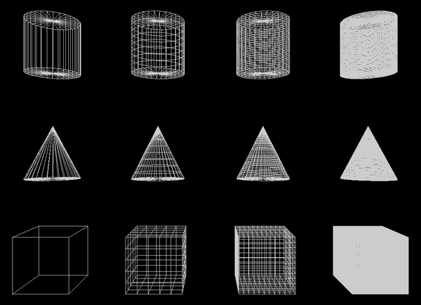
The example shows the cone, the cylinder and the cube with various triangulation. Leftmost column has no over-triangulation, next columns have more and more over-triangulation. We use our own extensions to control the triangulation, see Geometry3D component - extensions for details.
Spot lights shine on every object. First screenshot shows the wireframe view, so you can see how the triangulation looks like.
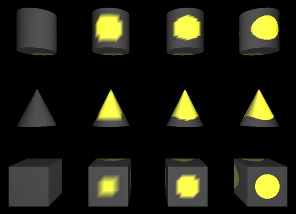
Now let's see the same example rendered using OpenGL (Gouraud shading). As you can see, on the leftmost column spot highlight is not visible at all. The more to the right and the spot looks better and better.
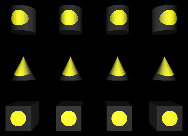
And finally let's see ray-tracer rendering of the same example. As you can see, over-triangulation (on boxes faces, and stacks on cones and cylinders) doesn't matter here at all.
If you want to control how detailed the triangulation should be:
Programmers can use
DefaultTriangulationSlices,DefaultTriangulationStacksandDefaultTriangulationDivisionsglobal variables.VRML / X3D authors can use the Geometry3D component - extensions: custom triangulation fields in node to control this.
Finally, my programs view3dscene and rayhunter allow you to control this by command-line options
--detail-quadric-slices <integer>
--detail-quadric-stacks <integer>
--detail-rect-divisions <integer>
| |  | |
| 3.6. Traversing VRML graph |  | 3.8. WWWBasePath property |